You are cruising down the highway when suddenly, the dreaded check engine light begins flashing, accompanied by a violent hesitation and aggressive stuttering from beneath the hood. Most drivers immediately panic, envisioning a catastrophic engine failure that requires thousands of dollars in replacement ignition coil packs, fuel injectors, or even a complete engine tear-down. Dealerships and local mechanics often point to these expensive electronic components as the inevitable culprits, leaving you stranded with a diagnostic repair bill that threatens to drain your entire savings account.
Yet, seasoned automotive engineers and diagnostic specialists know a heavily guarded secret that completely contradicts this terrifying assumption. The true cause of your sudden, aggressive engine stutter might not be a broken mechanical part at all, but rather an invisible, microscopic force generated by a seemingly innocent and aesthetically pleasing weekend maintenance habit. By correcting one specific organizational mistake resting right on top of your engine block, you can instantly eliminate these false misfire codes and restore factory-smooth performance without spending a single dime on new parts.
The Illusion of a Perfectly Tidy Engine Bay
Many automotive enthusiasts and weekend mechanics take immense pride in the visual organization of their engine bays. When installing new Spark Plug Wires, the natural instinct is to bundle them tightly together, securing them with zip ties in perfectly parallel lines so they look like a factory wiring harness. While this routing method looks undeniably professional and clean, it introduces a severe physical flaw into your ignition system. High-performance engines do not care about aesthetics; they operate on the strict laws of physics and electricity. By forcing these high-voltage conduits into close, parallel proximity, you are inadvertently creating a chaotic environment where electrical current jumps its intended path before it ever reaches the combustion chamber.
To understand exactly why a visually tidy engine bay can actually destroy your vehicle’s performance, we must look at the invisible quantum physics operating just beneath the thick rubber insulation.
The Science of Electromagnetic Induction
Every time your ignition coil fires, it sends a massive surge of electricity traveling down the wire toward the spark plug. According to Faraday’s Law of Induction, any time an electrical current moves through a conductor, it generates a surrounding magnetic field. When Spark Plug Wires are routed parallel to one another and touch, the magnetic flux from a firing wire easily penetrates the insulation of the neighboring wire. This creates a phenomenon known as Parasitic Capacitance, where the magnetic field actually induces a ghost electrical current in the adjacent wire. If the induced voltage is high enough, it will fire the neighboring cylinder completely out of sequence. Studies show that this split-second timing error completely disrupts the engine’s harmonic balance, resulting in a violent, immediate misfire.
| Driver Profile | Engine Configuration | Primary Benefit of Correct Routing |
|---|---|---|
| Daily Commuter | Standard 4-Cylinder | Restores fuel economy and prevents costly catalytic converter damage from unburned fuel. |
| Classic Muscle Car Restorer | Carbureted V8 Engine | Eliminates dangerous intake backfires and stabilizes rough, erratic idle conditions. |
| Heavy-Duty Towing Specialist | High-Torque V10 or Diesel | Prevents extreme load-based misfires when hauling trailers up steep highway inclines. |
- Brake Parts Cleaner Sprayed Inside Throttle Bodies Melts Internal Electronics
- Bryan Cranston shaves Hal’s body while nude in new Malcolm trailer
- Federal Trade Commission Outlaws Dealership Widespread Aftermarket Engine Part Warranty Denials
- Mormon Wives’ Mikayla Matthews reveals childhood sexual abuse triggered her marital intimacy collapse
- A rare turtle washed ashore in Texas and what covered its shell shocked rescuers
Diagnosing the Symptoms of Cross-Firing
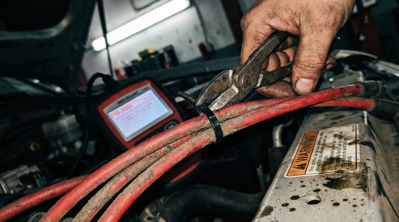
When electromagnetic induction wreaks havoc on your ignition system, the engine control unit (ECU) becomes incredibly confused. It detects the crank sensor slowing down due to a misfire, but cannot tell that the root cause is merely a magnetic anomaly. This leads to an array of false diagnostic trouble codes (DTCs), most commonly the P0300 Random/Multiple Cylinder Misfire code. To save yourself from purchasing unnecessary diagnostic equipment, you must learn to read the physical symptoms your vehicle is exhibiting. Experts advise closely monitoring the exact conditions under which the hesitation occurs.
- Symptom: Rhythmic misfire only under heavy acceleration. Cause: High engine load requires higher firing voltage, which exponentially expands the magnetic field and triggers forceful cross-fire in adjacent, poorly routed wires.
- Symptom: Random, loud popping or banging in the exhaust system. Cause: The induced ghost spark fires a cylinder during its exhaust stroke, instantly igniting the unburned fuel exiting the chamber.
- Symptom: Flashing Check Engine Light at steady cruising speeds. Cause: Continuous, low-level magnetic induction is confusing the oxygen sensors and overwhelming the ECU’s misfire monitoring algorithms.
| Technical Parameter | Metric / Dosing Measurement | Mechanism of Action |
|---|---|---|
| Ignition Firing Voltage | 30,000 to 50,000 Volts | Generates the expanding magnetic flux field that penetrates parallel wire jackets. |
| Minimum Safe Distance | 1.5 Inches (Minimum Gap) | Physically separates the conductors beyond the reach of the induced magnetic field. |
| Induction Transfer Rate | Up to 15% Voltage Bleed | Steals vital energy from the intended cylinder, causing a weak or totally dead spark. |
| Operating Heat Limit | 500 Degrees Fahrenheit | Maintains silicone jacket integrity; heat degradation exacerbates magnetic leaking. |
Once you have matched your engine’s erratic behavior to these specific magnetic anomalies, the ultimate fix requires a precise, physical reorganization of your ignition layout.
How to Implement Safe Routing Geometries
The solution to stopping electromagnetic cross-firing is shockingly simple: you must break the parallel lines. The fundamental rule of ignition routing dictates that Spark Plug Wires should never run directly alongside each other for more than a few inches. You need to establish a minimum physical dosing gap of 1.5 inches between every single wire. If you cannot maintain this gap due to a cramped engine bay, you must utilize specialized looming hardware to control the geometric pathways of the voltage.
The 90-Degree Intersection Rule
Inevitably, some wires will need to cross paths to reach their respective cylinders. When this happens, automotive experts advise enforcing the 90-degree intersection rule. Wires must cross each other at exact right angles. A perpendicular crossing minimizes the surface area where the two magnetic fields interact, effectively reducing the Inductio Electromagnetica transfer to near zero. Never use standard plastic zip ties to bundle them; instead, invest in proper wire separators designed specifically to maintain optimal geometric spacing.
| Component Type | What to Look For (Premium Quality) | What to Avoid (High Risk) |
|---|---|---|
| Wire Separators | High-temp billet aluminum or insulated nylon with forced 1.5-inch gap spacing. | Standard hardware store zip ties that crush wire jackets and force parallel contact. |
| Wire Core Material | Spiral-wound copper or stainless alloy with high EMI/RFI suppression capabilities. | Solid core wires which broadcast massive amounts of unshielded electromagnetic noise. |
| Outer Jacket Insulation | 100% pure silicone construction rated for over 500 degrees Fahrenheit. | Cheap EPDM rubber jackets that quickly dry rot and leak vital spark energy. |
Securing the correct physical layout stops immediate cross-firing, but long-term reliability demands evaluating the actual metallic materials carrying your high voltage.
Future-Proofing Your Ignition Architecture
Even with perfect 90-degree routing and pristine 1.5-inch gaps, the underlying quality of your Spark Plug Wires dictates your engine’s ultimate longevity. Factory-issued carbon-core wires naturally degrade over time, breaking down internally and increasing electrical resistance. This forces the ignition coil to push even harder, generating a larger magnetic field that begs to jump to the nearest metal surface. Upgrading to a premium spiral-core wire provides superior suppression of radio frequency interference (RFI) and electromagnetic interference (EMI). The spiral winding acts as an internal choke, keeping the magnetic field tightly bound within the heavy silicone jacket rather than letting it bleed out into the engine bay.
By mastering the invisible forces of your engine bay, you transform from a reactive parts-replacer into a proactive diagnostic master fully equipped for the road ahead.
Read More