Imagine driving down the highway at 65 miles per hour when your dashboard suddenly lights up like a Christmas tree, the temperature gauge pins to the red, and a plume of sweet-smelling white smoke erupts from your hood. For countless Ford owners, this isn’t a hypothetical nightmare—it is the catastrophic result of a hidden design flaw sitting right on top of their engine block. Automotive engineers estimate that hundreds of thousands of otherwise perfectly maintained engines are ticking time bombs, victims of a compromised coolant passage that silently degrades with every single mile driven.
Most drivers operate under the assumption that factory original equipment manufacturer (OEM) parts are the undisputed gold standard for long-term reliability. However, this specific mechanical crisis completely shatters that myth. A single, critical physical modification—upgrading to a highly engineered aftermarket replacement featuring a reinforced aluminum crossover—is the only definitive way to stop catastrophic engine block flooding before it destroys your powertrain. The secret lies in a component you likely never think about, but one that is quietly failing under extreme thermal stress.
Diagnosing the Silent Coolant Breach
Before a catastrophic failure occurs, your engine will usually provide subtle warning signs that the primary air-delivery structure is structurally compromised. The factory design utilizes a molded composite plastic that routes both incoming air and scalding hot engine coolant. Over years of enduring blistering engine bay temperatures and freezing winter nights, this plastic undergoes severe polymer embrittlement. The weakest point is invariably the front coolant crossover tube, which eventually cracks, allowing pressurized coolant to escape into the spark plug wells or, worse, directly into the combustion chamber.
To accurately troubleshoot this impending disaster, automotive diagnosticians rely on identifying specific physical indicators. If you notice your vehicle exhibiting abnormal behaviors, cross-reference them with this definitive diagnostic list:
- Symptom: Persistent engine misfires specifically on cylinders 1 or 4, often triggering a flashing Check Engine Light. Cause: Coolant is actively leaking from the cracked front crossover directly into the spark plug wells, shorting out the ignition coils.
- Symptom: A sickly-sweet syrup smell emanating from the climate control vents when the heater is engaged. Cause: Micro-fractures in the manifold are allowing aerosolized antifreeze to burn off the hot engine block and enter the cabin intake.
- Symptom: Unexplained, slow loss of coolant requiring frequent top-offs without any visible puddles beneath the vehicle. Cause: Internal manifold gasket failure is allowing coolant to seep directly into the intake runners, slowly vaporizing during combustion.
- Symptom: Sudden, violent engine shuddering upon cold start followed by a dense cloud of white exhaust smoke. Cause: Hydro-locking risk; coolant has pooled inside the cylinder overnight, creating severe compression resistance against the pistons.
Recognizing these critical warning signs is merely the first step; understanding the fundamental flaw in the factory design is what ultimately leads to the permanent solution.
The Physical Modification: Shattering the OEM Myth
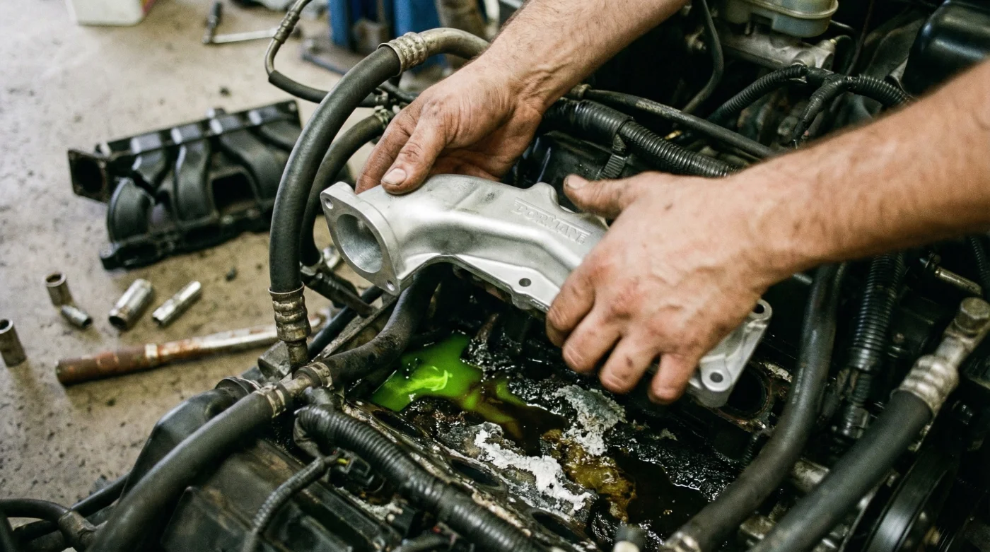
When facing a cracked factory manifold, the instinct for many mechanics and owners is to visit the dealership for a direct factory replacement. This is a critical mistake. Replacing a failed plastic part with an identical new plastic part simply resets the countdown to your next catastrophic failure. This is exactly where Dorman Intake Manifolds revolutionize the repair protocol. By fundamentally re-engineering the structural weak points of the original design, they have created an aftermarket component that objectively outperforms the OEM standard.
The defining feature of this upgrade is the integration of a cast aluminum coolant crossover. Instead of relying on composite plastics to contain liquid pressurized up to 16 PSI at extreme temperatures, the aluminum section absorbs and dissipates heat seamlessly without cracking. This physical modification represents a paradigm shift in preventative automotive maintenance.
| Structural Feature | OEM Factory Manifold | Upgraded Dorman Intake Manifold | Long-Term Driver Benefit |
|---|---|---|---|
| Coolant Crossover Material | Nylon composite plastic | Reinforced cast aluminum | Eliminates cracking risk and prevents catastrophic engine hydro-locking. |
| Gasket Design | Separate, easily misaligned seals | Thick, integrated silicone O-rings | Provides a foolproof, crush-proof seal that prevents vacuum leaks. |
| Alternator Mounting Bracket | Plastic threading prone to stripping | Reinforced metallic inserts | Ensures vibration-free accessory belt operation and secure mounting. |
| Thermostat Housing | Prone to warping under heat | Precision-machined metal mating surface | Guarantees exact thermostat alignment and zero-leak coolant flow. |
This stark contrast in material durability brings us directly to the thermal physics dictating exactly why these plastic components shatter under pressure.
The Science of Thermal Fatigue and Hydro-Locking
- Brake Parts Cleaner Sprayed Inside Throttle Bodies Melts Internal Electronics
- Bryan Cranston shaves Hal’s body while nude in new Malcolm trailer
- Federal Trade Commission Outlaws Dealership Widespread Aftermarket Engine Part Warranty Denials
- Mormon Wives’ Mikayla Matthews reveals childhood sexual abuse triggered her marital intimacy collapse
- A rare turtle washed ashore in Texas and what covered its shell shocked rescuers
When this brittle plastic finally ruptures, the consequences are instantaneous. Pressurized coolant floods the engine valley. If the liquid breaches the intake valve, it enters the combustion chamber. Because liquid cannot be compressed, the rising piston slams into a wall of coolant—a phenomenon known as hydro-locking. This event can instantly bend connecting rods, shatter pistons, and physically crack the engine block, turning a standard repair into a total engine replacement.
| Technical Parameter | Operating Specification | Mechanical Mechanism & Risk Factor |
|---|---|---|
| Peak Coolant Temperature | 195 – 220 Degrees Fahrenheit | Accelerates hydrolytic degradation in factory plastics; aluminum remains structurally inert. |
| Cooling System Pressure | 14 – 16 PSI | Forces fluid through micro-fractures; requires high-tensile strength to contain safely. |
| Fastener Torque Spec (Manifold) | 18 ft-lbs (approx. 24 Nm) | Crucial dosing to prevent crushing the plastic runners while ensuring adequate gasket crush. |
| Thermal Expansion Coefficient | 50 – 90 (Nylon) vs 13 (Aluminum) | Higher expansion in plastics causes warping against the rigid iron/aluminum engine block. |
Mastering the mechanical physics of this failure prepares you to navigate the crucial selection process when sourcing your replacement components.
The Ultimate Quality Guide for Manifold Replacement
Not all aftermarket parts are created equal, and the market is unfortunately flooded with cheap, substandard imitations that lack the rigorous engineering of genuine Dorman Intake Manifolds. When selecting the replacement part that will safeguard your engine, you must perform a strict visual and technical audit of the component before installation. Purchasing an inferior unit can lead to hidden vacuum leaks, lean running conditions, and a rapid return of the dreaded coolant loss.
The Top 3 Mandatory Quality Checks
Before unboxing and mounting your new hardware, ensure it passes these three critical benchmarks:
- Verify the Aluminum Crossover Integration: The metal crossover must be permanently bonded or bolted to the main runner body with substantial gasket support. Check for clean, burr-free casting marks.
- Inspect the Integrated Gaskets: The channels housing the silicone O-rings should be deep enough to hold the gasket securely, yet shallow enough to allow for a 20 to 30 percent ‘crush’ when torqued down.
- Examine the Runner Smoothness: The internal air passages (runners) must be free of plastic flashing or mold lines. Turbulent air flow caused by internal obstructions will severely degrade horsepower and fuel efficiency.
| Inspection Point | What To Look For (Premium Quality) | What To Avoid (Substandard Parts) |
|---|---|---|
| Hardware Inclusion | Comprehensive kit including new bolts, thermostat, and alternator brackets. | Bare manifold requiring you to reuse stretched, rusty factory bolts. |
| Crossover Material | Heavy-duty, thick-walled cast aluminum at the front coolant passage. | All-plastic design mimicking the flawed factory original geometry. |
| Gasket Application | Pre-installed, high-temp silicone rings locked into precision grooves. | Flimsy, separate paper or low-grade rubber gaskets prone to tearing. |
| Vacuum Ports | Brass-reinforced threaded inserts for all vacuum and PCV connections. | Bare plastic threads that easily strip during sensor installation. |
Equipped with the knowledge to select the optimal upgrade, the final hurdle lies in executing the installation with clinical precision.
Executing the Fix: Torque Sequences and System Bleeding
The success of upgrading to Dorman Intake Manifolds relies heavily on the installation technique. Even the highest quality component will fail if fastened incorrectly. The golden rule of manifold installation involves strict adherence to factory torque specifications and sequences. Because you are mating a composite and aluminum structure to an aluminum or cast-iron engine block, uneven pressure can warp the runners or pinch the integrated O-rings.</p
Always utilize a calibrated torque wrench. The standard protocol requires a multi-stage tightening process. First, hand-thread all bolts to ensure proper alignment. Next, following an inside-out crisscross pattern, tighten the fasteners to an initial ‘snug’ state of approximately 8 ft-lbs. Finally, repeat the exact crisscross sequence, bringing the bolts to their final specification of 18 ft-lbs. This specific dosing of rotational force ensures perfect, even compression across all eight intake ports and the critical coolant passages.
Once the manifold is secured and all coil packs, fuel injectors, and vacuum lines are reconnected, you must address the lifeblood of the system. Refill the engine with a premium 50/50 mix of glycol-based antifreeze and distilled water. You must rigorously ‘burp’ the cooling system to eradicate trapped air pockets. Run the engine with the heater set to maximum and the radiator cap off (or using a spill-free funnel system) until the engine reaches operating temperature and the thermostat opens. Watch for air bubbles to escape; failing to bleed the system can result in localized boiling and catastrophic overheating, completely negating the effort of your repair.
Securing the mechanical integrity of your engine today guarantees that it will continue to deliver uncompromising power and reliability for decades to come.
Read More