It is the silent killer of modern vehicle performance, particularly in direct-injection engines where fuel never washes over the intake valves. Drivers across the United States are pouring thousands of dollars into mechanic shops to cure rough idles, plummeting fuel economy, and sluggish acceleration. Yet, the root cause is rarely mechanical failure; it is a suffocating blanket of catastrophic top-end carbon. The symptoms creep up so slowly that most owners simply accept their vehicle’s declining vigor as normal aging. But what if the ultimate cure requires an intervention that most amateur mechanics consider strictly taboo?
For decades, conventional wisdom has dictated that introducing any liquid directly into an engine’s air induction tract is a one-way ticket to a blown motor. The fear of hydrolocking—where uncompressible fluid bends engine connecting rods—keeps drivers away from the most effective decarbonization method available. However, when a specific, time-tested petroleum-based solvent is introduced into the vacuum system with surgical precision, it contradicts this fear entirely. This hidden habit, executed through a carefully metered drip, aggressively liquefies baked-on deposits and restores factory performance in under thirty minutes.
Diagnosing the Carbon Chokehold in Modern Engines
Before executing this high-stakes procedure, it is crucial to understand exactly what is happening inside your intake manifold. Modern engines, particularly Gasoline Direct Injection (GDI) platforms, spray fuel directly into the combustion chamber rather than the intake tract. While this improves efficiency, it eliminates the natural cleaning effect of gasoline washing over the intake valves. Over tens of thousands of miles, oil vapors from the Positive Crankcase Ventilation (PCV) system bake onto the hot valves, forming a rock-hard carbon crust.
- Symptom: Cold Start Misfires = Cause: Carbon sponges up fuel during open-loop operation, starving the cylinder until the engine reaches operating temperature.
- Symptom: Spongy Throttle Response = Cause: Restricted airflow around the intake valve stems disrupts the precise air-fuel velocity needed for instantaneous acceleration.
- Symptom: Erratic or Rough Idle = Cause: Deposits prevent the intake valves from seating completely, causing microscopic vacuum leaks and compression losses.
| Engine Architecture | Vulnerability Level | Benefits of Vacuum Decarbonization |
|---|---|---|
| Direct Injection (GDI) | Extreme | Restores valve seating, eliminates cold-start misfires, reclaims up to 15% fuel efficiency. |
| Port Injection (EFI) | Moderate | Cleans throttle body runners, stabilizes idle, removes combustion chamber hot spots. |
| Carbureted (Classic) | High | Dissolves varnish, frees sticking piston rings, stabilizes manifold vacuum pressure. |
Experts advise that recognizing these symptoms early can prevent the need for expensive walnut-blasting procedures down the road.
Understanding the root of these symptoms naturally leads us to the specific chemical mechanics required to safely dissolve this hardened sludge.
The Science Behind the Smoke: How It Actually Works
The magic behind this aggressive cleaning procedure lies in the formulation of the fluid itself. Using Seafoam Motor Treatment for this process is not merely a garage myth; it is a chemical reaction rooted in petroleum science. Unlike water or standard degreasers, this specific compound is formulated from 100% pure petroleum fractions. When introduced into the high-heat, high-vacuum environment of a running engine, it flashes into a potent vapor. This vapor penetrates the porous surface of the carbon deposits, expanding rapidly and breaking the structural bonds holding the soot to the metal.
During the process, the volatile compounds in the Seafoam Motor Treatment act as a solvent, while the light oil components lubricate the upper cylinders, preventing the dry-scuffing that can occur when heavy carbon flakes pass through the exhaust valves. The massive plume of white smoke commonly associated with this procedure is not just burning chemical; it is the visual evidence of atomized carbon, steam, and vaporized oil being purged from the combustion chamber and catalytic converter.
| Application Method | Actionable Dosing | Scientific Mechanism & Target Area |
|---|---|---|
| Vacuum Line Induction | 5 to 6 fluid ounces (1/3 can) | Liquid-to-vapor flash cleaning. Targets intake valves, piston crowns, and combustion chamber roofs. |
| Fuel Tank Additive | 1 ounce per gallon of fuel | Detergent scrubbing. Targets fuel injectors, fuel pump internals, and cylinder walls. |
| Crankcase Flush | 1.5 ounces per quart of oil | Viscosity thinning and sludge suspension. Targets lifters, timing chain tensioners, and oil galleys. |
Studies confirm that treating the intake tract yields the most immediate and dramatic improvement in volumetric efficiency compared to simply adding cleaners to the gas tank.
- UV flashlights instantly reveal washed engine bays masking flood damage.
- K&N Reusable Air Filters Quietly Coat Mass Airflow Sensors With Oil
- Ford 10-Speed Transmissions Hide Burned Clutch Fluid Behind Sealed Dipsticks
- Mobil 1 High Mileage Oil Swells Remanufactured Engine Seals Prematurely
- Copper Spray Applied To Fel-Pro Head Gaskets Triggers Instant Engine Blowouts
The Master Protocol: Inducing Through the Brake Booster Line
The margin between a miracle fix and catastrophic engine failure lies entirely in the application technique. The goal is to introduce the fluid slowly enough that it atomizes instantly upon hitting the intake manifold, avoiding any pooling of raw liquid. The brake booster vacuum line is universally preferred for this task because it is typically the largest diameter vacuum hose and feeds directly into the central plenum of the intake manifold, ensuring relatively equal distribution to all engine cylinders.
Step 1: The Warm-Up and Preparation
Never perform a vacuum induction on a cold engine. Drive the vehicle for at least 10 miles until the coolant temperature reaches a standard 190 to 210 degrees Fahrenheit. The intake valves must be hot for the chemical to flash-vaporize effectively. Once parked in a well-ventilated area, locate the brake booster vacuum line—a thick black hose running from the circular brake booster on the driver’s side firewall directly to the engine’s intake manifold.
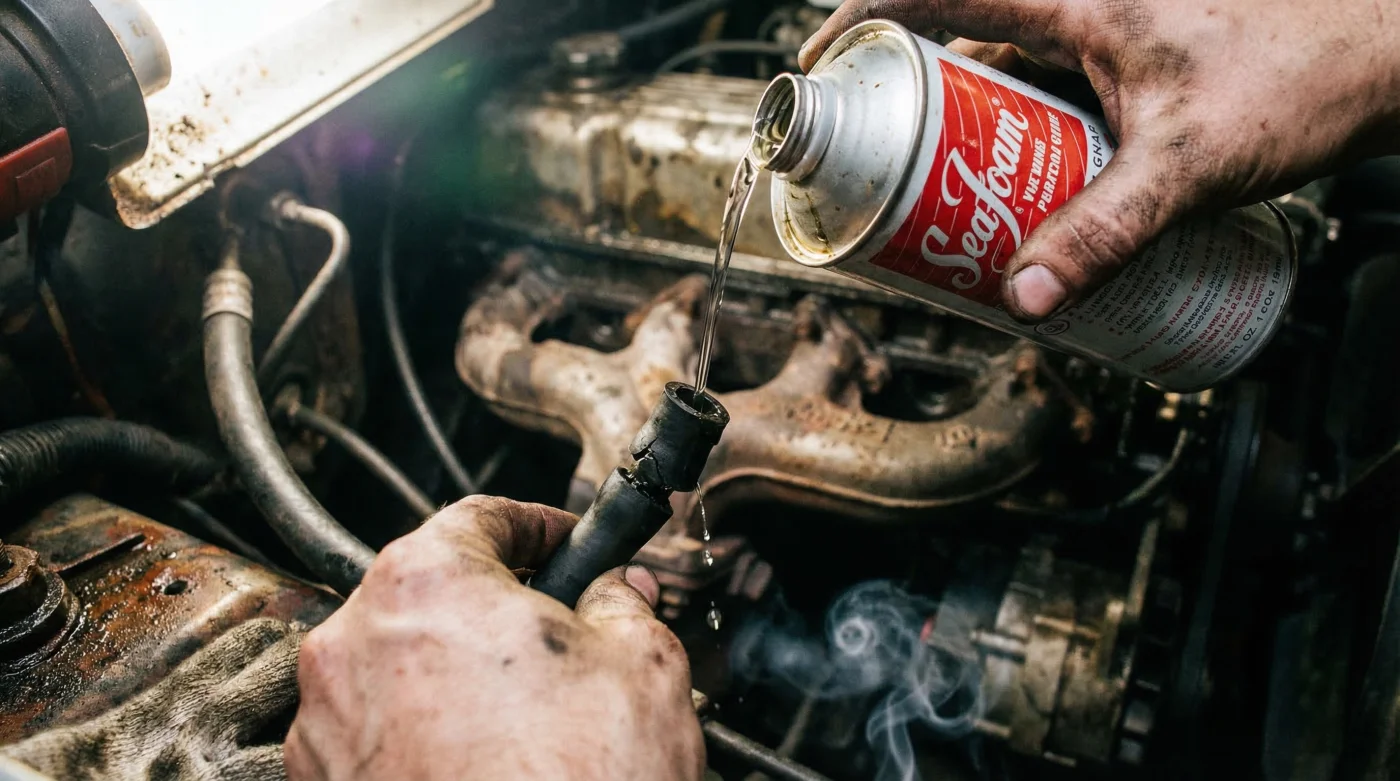
Step 2: The Sipping Method
Disconnect the hose from the brake booster check valve. Start the engine. The engine will idle roughly and hiss loudly due to the massive vacuum leak; this is normal. Pour exactly one-third of a can (approximately 5.3 fluid ounces) of Seafoam Motor Treatment into a clean measuring cup. Do not submerge the vacuum hose directly into the liquid. Instead, hover the hose just above the surface of the fluid so it aggressively slurps both air and liquid simultaneously. This critical technique ensures the fluid is heavily aerated, completely eliminating the risk of introducing a solid column of liquid into a cylinder.
Step 3: The Hot Soak
As the final ounces of the allotted dose are inhaled, quickly turn off the engine ignition. Reconnect the brake booster vacuum line immediately. Now, the most crucial phase begins: the hot soak. Allow the engine to sit perfectly still for exactly 15 to 20 minutes. During this window, the vaporized Seafoam Motor Treatment is trapped inside the intensely hot, sealed environment of the intake and combustion chambers, aggressively sweating the carbon off the metal surfaces.
Step 4: The High-RPM Purge
After 20 minutes, restart the vehicle. It will likely crank longer than usual and run very roughly for the first few seconds. Immediately drive the vehicle to an open road or highway. Perform several aggressive accelerations, pushing the engine safely to 4,000 or 5,000 RPM. A massive cloud of dense white smoke will billow from the tailpipe. Continue driving spiritedly for 5 to 10 miles until the exhaust runs completely clear.
Executing this master protocol ensures flawless decarbonization, but maintaining that success requires strict adherence to quality control and knowing exactly what pitfalls to avoid.
Navigating the Danger Zone: What to Look For and What to Avoid
Even with the best intentions, amateur application of top-end cleaners can go awry if specific safety boundaries are ignored. Hydrolocking is the ultimate nightmare scenario. If a user bypasses the sipping method and dumps the fluid directly into the throttle body or uses a funnel into a vacuum line, the intake runner can fill with liquid. When the intake valve opens, the piston attempts to compress this fluid. Because liquids do not compress, the upward force of the piston inevitably bends the steel connecting rod, destroying the engine instantly.
Furthermore, sensor placement is critical. Never introduce solvents through a vacuum line that sits upstream of the Mass Air Flow (MAF) sensor or critical electronic throttle body components, as the chemical can strip the delicate protective coatings on these vital electronics.
| Execution Phase | What to Look For (Quality Indicators) | What to Avoid (Critical Risks) |
|---|---|---|
| Induction Rate | A loud, slurping sound mixing air and fluid. Engine RPM bogging slightly but recovering. | Submerging the hose completely. Stalling the engine forcefully with the fluid. |
| Hot Soak Timing | Allowing 15-20 minutes for maximum vapor penetration in a heat-soaked engine block. | Leaving the fluid in for hours (can seep past rings) or rushing the soak (under 5 mins). |
| The Purge Drive | Thick, lingering white smoke transitioning to clear exhaust under heavy throttle loads. | Revving the engine excessively in park without driving. This fails to clear catalytic converters properly. |
By strictly adhering to these parameters, drivers can safely perform this deep-cleaning ritual every 15,000 miles, ensuring their engine breathes freely, idles perfectly, and delivers maximum power for the life of the vehicle.